Best Simulink Modeling Guides to Buy in January 2026

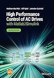
High Performance Control of AC Drives with Matlab/Simulink


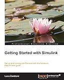
Getting Started with Simulink


Steuerung über FPGA mittels RS-232-Schnittstelle und Optimierung mit MatLab / Simulink: Fernsteuerung des ASURO-Roboters mittels FPGA und serieller Schnittstelle (German Edition)


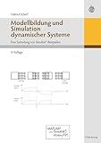
Modellbildung Und Simulation Dynamischer Systeme: Eine Sammlung von Simulink-Beispielen (German Edition)


Control Engineering: MATLAB Exercises (Advanced Textbooks in Control and Signal Processing)


To create a Simulink model in MATLAB, follow these steps:
- Launch MATLAB: Open the MATLAB software on your computer.
- Open Simulink Library Browser: In the MATLAB command window, type "simulink" and press Enter. This will open the Simulink Library Browser.
- Start a new model: In the Simulink Library Browser, click on "File" and select "New" and then "Model." This will create a new model window.
- Add blocks to the model: In the model window, browse the Simulink Library Browser to find the blocks you need for your model. Drag and drop the blocks from the Library Browser into the model window to add them.
- Connect blocks: To connect blocks together, click on a block's output port and drag a line to another block's input port. This will create a connection between the two blocks.
- Configure block parameters: To set parameters for a block, double-click on the block in the model window. This will open a dialog box where you can adjust the block's settings.
- Save the model: Click on "File" in the model window's menu bar and select "Save As" to save your Simulink model to a desired location on your computer.
- Simulate the model: To run the simulation, click on the "Run" button in the Simulink model window's toolbar. This will execute the model and display the simulation results.
- Analyze the results: After the simulation completes, you can analyze the results by plotting signals or using MATLAB functions and scripts.
- Continue refining the model: You can further modify the model by adding or removing blocks, adjusting parameters, and running additional simulations as needed.
That's it! These steps will help you create a Simulink model in MATLAB and simulate it to analyze the system behavior.
What are the different types of Simulink blocks available in MATLAB?
Simulink blocks in MATLAB provide various functionalities to model and simulate dynamic systems. Some of the commonly used Simulink blocks are:
- Sources: These blocks generate signals or input for the system. Examples include Constant, Step, Ramp, Sine Wave, etc.
- Sinks: These blocks display or record simulation results. Examples include Scope, To Workspace, Display, etc.
- Math Operations: These blocks perform mathematical operations on input signals. Examples include Add, Subtract, Product, Integrator, etc.
- Logic and Bitwise Operations: These blocks perform logical or bitwise operations on input signals. Examples include Logical Operator, Bitwise Operator, etc.
- Transfer Functions: These blocks represent linear time-invariant (LTI) systems or dynamic equations. Examples include Transfer Function, State-Space, Zero-Pole, etc.
- Continuous and Discrete Dynamics: These blocks model continuous-time or discrete-time dynamic systems. Examples include Integrator, Derivative, Discrete Integrator, Discrete State-Space, etc.
- Filters: These blocks implement various types of filters for signal processing. Examples include Lowpass Filter, Highpass Filter, Bandpass Filter, etc.
- Timers and Delays: These blocks introduce time delays in the simulation. Examples include Constant Delay, Variable Time Delay, etc.
- Lookup Tables: These blocks handle non-linear relationships using lookup tables. Examples include 1D Lookup Table, 2D Lookup Table, etc.
- Control Systems: These blocks model and simulate control systems. Examples include PID Controller, State Feedback, Transfer Fcn, etc.
These are just a few examples, and Simulink provides many more blocks to cater to various modeling and simulation requirements.
What is the role of masks in Simulink models?
Masks in Simulink models provide a way to hide, customize, and encapsulate blocks within a model.
The primary role of masks is to hide the details of a block, allowing users to focus on high-level functionality. By creating a mask, the user can define custom parameter fields and display only the necessary inputs and outputs on the block, thereby reducing clutter and making the model more understandable.
Masks also enable users to customize the appearance and behavior of blocks. Users can define icon and port labels, specify default parameter values, and create custom dialogue boxes for block settings. This allows for a more intuitive and user-friendly interface when working with complex blocks or subsystems.
Additionally, masks provide a way to encapsulate complex subsystems or libraries of blocks into a single block, abstracting the internal implementation details. This allows for reuse of commonly used subsystems, improves modularity, and simplifies the overall model structure.
In summary, masks in Simulink models play a vital role in hiding, customizing, and encapsulating blocks, thereby improving the readability, flexibility, and reusability of the model.
How to add blocks to a Simulink model?
To add blocks to a Simulink model, you can follow these steps:
- Open the Simulink library browser by either clicking on the icon in the Simulink toolbar or by selecting "Library Browser" from the "View" menu.
- In the library browser, navigate and select the library that contains the block you want to add. The library browser contains various libraries organized into categories such as Simulink, Sources, Sinks, Math Operations, etc.
- Once you have selected the library, it will display the blocks available in that library. You can search for a specific block by typing its name or filter the blocks based on categories.
- To add a block to your Simulink model, simply drag and drop the block from the library browser into your model window.
- Customize the block's parameters by double-clicking on the block or right-clicking and selecting "Block Parameters". This will open a dialog box where you can modify the block's properties and configure its inputs/outputs, sample times, etc.
- Repeat the process to add more blocks to your Simulink model as needed.
Remember to connect the inputs and outputs of the blocks appropriately by using the connectors that appear when you hover over a block's input/output ports. This will define the flow of signals in your model and enable the simulation.
